![]() The conceptual
background
The conceptual
background
![]()
![]() The track system
The track system
![]()
![]() The operating principle
The operating principle
![]()
![]() The interbus system
The interbus system
![]()
![]() The control program
The control program
![]()
![]() Some photographs
Some photographs
The model train system
Communicating control and sensor signals
The track system is connected via a so-called interbus system to the serial interface RS232 of a SUN UltraSPARC 10 worksation which runs the control program. The interbus communicates sensor data about train positions from the tracks to the workstation and control data from the worksation to individual track sections, switches and light signals. The data transfer rate is limited by the serial interface to 153,6 kilobit per second. This rate, in conjunction with the time it takes to run the control program, suffices to safely operate the trains with a delay between sensor data received and control data issued of some 70 milliseconds on average, during which time a train at full speed travels about 2 centimeters.
The topology of the interbus is schematically shown below. It comprizes a bus master which communicates data between the workstation on the on hand and several slaves that are connected in series to the bus on the other hand. The bus works like a cyclic shift register which transfers data from and to the master step by step through the slaves. Each slave is equipped with four shift registers, of which two - an input and an output register - get involved in data transfers, and another two - an identification and a control register - serve to identify the slaves that participate in a data transfer cycle.
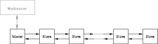
the interbus diagram
A typical data transfer cycle begins with the workstation sending to the bus master a frame of bytes which includes an instruction code, the number of data packets to be transmitted, some loopback code, the data packets themselves, ordered in the sequence in which they have to be picked up by the slaves, and some error correcting code. The loopback code followed by the data packets is then moved step by step through the slaves; they count the data packets that are passing through, accept the ones that match their numbers along the bus (with the first packet moving all the way through to the last slave), and replace them with encoded sensor data. The loopback code arriving at the last slave of the bus reverses direction and moves the sensor data in reverse order to the master. The bus cycle is complete with the loopback code returning to the master, which then forwards the data chain to the workstation.
The hardware implementation of the bus system has two slave units accommodated on a single slave board. The on-board input and output shift registers are shared between both units; both have 3 bytes (or 24 bits) length, which determines the length of the data packets. Each slave unit serves one section of track, with up to two switches, two signals (three light emitting diodes each) and two pairs of reed contacts. It transforms incoming control data into pulse-width modulated DC voltages (speed levels) for the two track sections, into on/off voltages for the signal lights, and into currents of about one ampere that drive the magnetic coils of the switches. Likewise, it puts sensor signals received from the reed contacts into outgoing data packets. Incoming control data packets of 24 bits length are accordingly partitioned into 12 bits for signal lights, 4 bits for switches, and 8 bits for speed levels. Outgoing sensor data packets use only the last 8 bits of the 24 bit format.
22.07.2003